Transparent Part Injection Molding: Materials, Mold Design & Defect Prevention
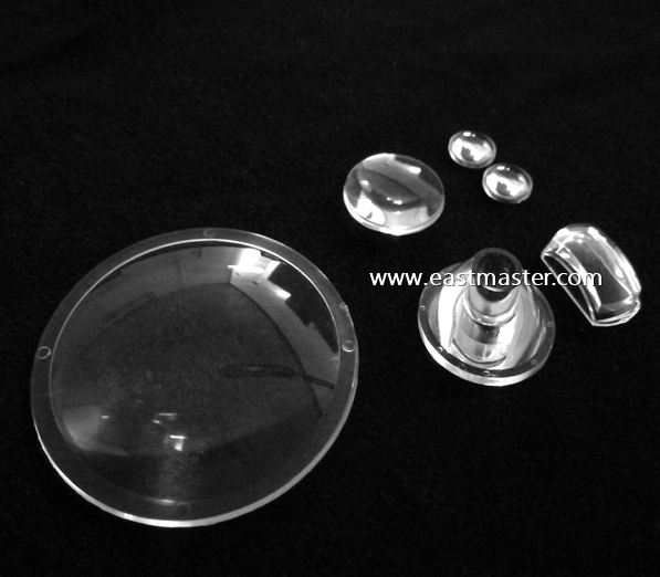
Transparent plastic parts are everywhere — car lights, medical device windows, display covers, lenses, and food packaging. But molding clear parts is one of the hardest jobs in injection molding. Any tiny defect that would be invisible on a colored part shows up clearly on a transparent one.
This guide covers the materials, mold design, process tips, and defect prevention for clear plastic injection molding. Based on years of manufacturing experience at Eastmaster Manufacturing Limited in Shenzhen, China.
Materials for Transparent Parts
Not all plastics can be transparent. The three most common clear plastics for injection molding are:
• Polycarbonate (PC): Very strong and impact resistant. Good heat resistance (up to 130°C). Used for car lights, safety glasses, medical devices. Absorbs moisture — must be dried before molding.
• PMMA / Acrylic: Best optical clarity (up to 92% light transmission). Good UV resistance. Used for lenses, display panels, light covers. More brittle than PC — cracks more easily.
• Transparent ABS / PS: Lower cost option. Good for consumer product windows and packaging. Lower heat resistance than PC or PMMA.
Materials like Nylon, PEEK, and PTFE are not used for transparent parts. These engineering plastics are chosen for strength and heat resistance, not clarity.
Mold Design for Clear Parts
The mold is the single most important factor for transparent part quality.
Mirror Polish (SPI A-1 or A-2)
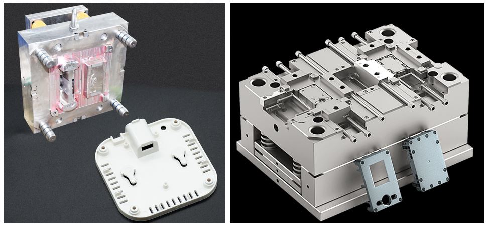
The cavity surface must be polished to a mirror finish. Any scratch or mark on the mold shows up directly on the part. Diamond buffing is the standard process, reducing surface roughness to fractions of a micrometer. A well-polished mold also reduces the risk of the part sticking during ejection.
Gate Design
• Place the gate outside the visible area when possible
• Use wide, shallow gates to reduce flow marks
• Avoid small gates that cause high shear stress and visible jetting
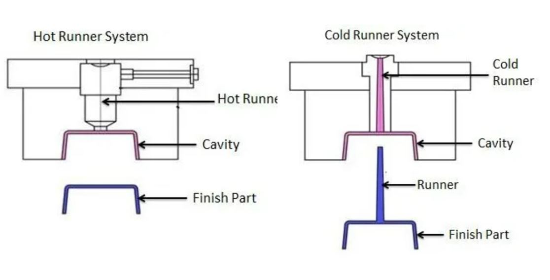
• Hot runner systems help keep melt temperature consistent across the cavity
Uniform Wall Thickness
Uneven walls cause uneven cooling, which leads to internal stress and optical distortion (birefringence). Keep walls as even as possible and use gradual transitions (3:1 ratio minimum) when thickness changes are needed.
Draft Angles
Use draft angles of 2 degrees or more for clear parts. Small draft angles cause sticking during ejection, which can scratch or crack the clear surface. This is especially important for textured surfaces where friction is higher.
Cooling System
Consistent mold temperature is critical. Temperature differences above 10°C between cavity and core cause uneven shrinkage and optical defects. Use conformal cooling channels for complex geometry, or reposition baffles in problem zones on existing tooling.
Key Process Parameters
Material Drying — Critical for Clear Parts
PC and PMMA absorb moisture from the air. Even 0.02% moisture can cause visible bubbles and cloudiness in a clear part. Standard drying requirements:
• PC: 120°C for 3-4 hours, moisture content below 0.02%
• PMMA: 80-85°C for 2-3 hours, moisture content below 0.05%
• Use a desiccant dryer: Standard hopper dryers are rarely sufficient for optical-grade parts. Desiccant dryers reaching -40°C dew point are the standard.
Injection Speed
Use moderate injection speed. Too fast causes flow lines and birefringence (molecular stress that shows as double refraction). Too slow causes the melt to cool before filling the cavity completely.
Melt Temperature
Keep melt temperature within the material's recommended range. Too high causes degradation and yellowing. Too low causes flow marks and incomplete filling.
Mold Temperature
Higher mold temperature improves surface replication and reduces flow marks, but increases cycle time. For amorphous materials like PC and PMMA, higher mold temperature also reduces the risk of haze.
Packing Pressure
Use multi-stage packing pressure. Start with higher pressure and decrease in stages. This compensates for shrinkage without over-stressing the part. Hold pressure until the gate freezes.
Common Defects and How to Fix Them
|
Defect |
Cause |
Fix |
|
Bubbles and Voids |
Moisture in material or trapped air |
Dry material properly. Lower injection speed. Increase packing pressure. |
|
Flow Lines |
Uneven melt flow in the cavity |
Improve gate design. Use hot runner. Adjust melt and mold temperature. |
|
Haze and Cloudiness |
Internal stress or moisture |
Dry material. Use faster cooling. Increase mold temperature for amorphous materials. |
|
Birefringence |
Residual stress from high-speed injection |
Lower injection speed. Use uniform wall thickness. Maintain consistent cooling. |
|
Scratches |
Ejection or handling damage |
Increase draft angles. Use proper ejection system. Handle with clean gloves. |
|
Yellowing |
Melt temperature too high or material degradation |
Reduce melt temperature. Check for contaminated material. Add UV stabilizers if needed. |
Post-Molding Handling
Clear parts need careful handling after molding to maintain optical quality:
• Use clean, lint-free gloves when handling
• Store in protective packaging immediately after molding
• Avoid stacking parts without separators
• Clean with appropriate solvents only — no abrasive cleaners
• Inspect under proper lighting (800+ lux angled light) to catch subtle defects
When to Choose CNC Machining for Clear Parts
For low-volume transparent parts, CNC machining from clear plastic stock (PC, PMMA) can be a good option:
• No mold cost — saves significant upfront investment
• Faster for prototypes and small batches (days vs. weeks)
• Can achieve optical-quality finish with proper polishing
• Good for validating the design before committing to a mold
Our prototyping service can produce clear CNC machined parts for design validation before full production molding.
Why Choose Eastmaster for Transparent Parts
At Eastmaster Manufacturing Limited, we understand that transparent parts demand a higher level of process control. From material drying to mold polishing to post-molding handling, every step matters.
• SPI A-1 mirror polish capability on all clear part molds
• Desiccant drying systems for all hygroscopic clear materials
• Clean handling and packaging procedures for optical parts
• Free DFM review to catch optical-risk geometry early
• CNC machining and prototyping for design validation
• ISO 9001 and ISO 13485 certified quality management
• D-U-N-S verified: 66-849-8033
Contact Eastmaster with your part drawings for a free DFM review and quote — typically within 24 hours.

• Email: info@eastmaster.com
• Phone: +86 755 22676100
• WhatsApp / WeChat available on the right side.
Stainless Steel CNC Machining: 303 vs 304 vs 316 Complete Comparison Guide
Thick Wall Injection Molding: Design Rules, Defects & Solutions Guide