ISO 2768 vs ISO 20457: General Tolerances in 2026
Not every CNC machining order arrives with a fully toleranced 2D drawing. Plenty of parts are quoted from a STEP file, a sketch, or a photo with a few numbers written on it. In that case every dimension you did not tolerance still has a value attached to it, and that value comes from a general tolerance standard. Getting the right one decides whether the parts pass inspection or come back.
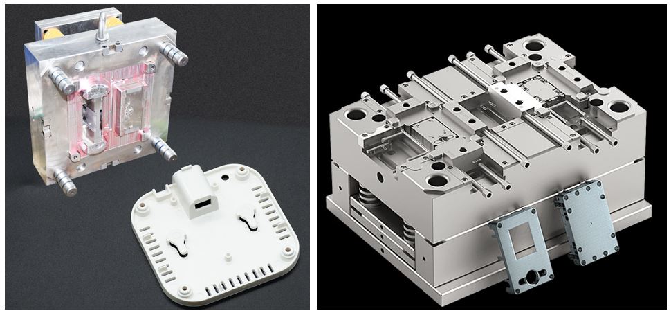
Two standards get quoted in this situation, and one of them is quoted wrongly almost everywhere online. ISO 2768 governs machined parts. ISO 20457 governs moulded plastic parts — injection, compression, transfer, rotational — and does not cover parts cut from solid stock. That distinction is not academic: it decides which table a buyer and a supplier are arguing about when a plastic part measures out of tolerance.
The standards themselves also moved recently. ISO 2768-1:1989 was withdrawn on 9 November 2026 and is being replaced by a single-part Edition 2. ISO 2768-2 disappeared back in 2021. This page sets out where each standard stands today, what to write on a drawing, and what actually governs a machined plastic part now that neither ISO 20457 nor the old DIN 16901 applies to it.
What a General Tolerance Actually Does
An untoleranced dimension does not mean "make it as accurate as you can". It means a default deviation applies, defined by whichever standard the drawing cites. Without that citation the number on the drawing has no acceptance limit, and the shop and the buyer fill the gap with different assumptions.
Ambiguity: the designer has ±0.05 mm in mind, the machinist plans for ±0.20 mm, and the parts get rejected at incoming inspection
Inconsistency: two operators on two machines apply two different defaults to the same feature
Cost: a shop that cannot tell which features matter will machine all of them tightly, and you pay for the ones that did not need it
Disputes: without a cited standard there is no reference to settle an argument, only opinion
A cited standard converts all four into a written number. That is the whole value — not precision, but a shared definition of acceptable.
ISO 2768 in November 2026: What Just Changed
ISO 2768-1:1989 was withdrawn on 9 November 2026. Its replacement is ISO 2768, Edition 2, which entered the publication stage on 2 June 2026 and is currently listed at stage 60.00 — final production, up to seven weeks. For a short window there is no published successor formally in force, which is itself a reason to put the edition on the drawing rather than the standard number alone.
Edition 2 keeps the linear and angular tables unchanged. What it changes is scope and interpretation, and four of those changes matter on a shop floor:
Scope narrows to linear and angular sizes only. Geometrical defaults leave ISO 2768 entirely and sit in the ISO 22081 framework
The broken-edge table is deleted. The old Table 2 gave default deviations for external radii and chamfer heights; Edition 2 removes those limits and does not replace them inside the standard
Clause 6 is deleted. In the 1989 text, a workpiece outside the general tolerance was not automatically rejected provided its function was not impaired. That protection is gone — an overshoot is now an overshoot
Scope also excludes distances and theoretically exact dimensions. A hole diameter is a linear size and falls under the table; a hole-centre location or a step height is a distance, and general tolerances do not cover it — those need their own callout
The practical consequence: an old drawing carrying "ISO 2768-m" still reads correctly for its linear dimensions, because the numbers did not move. But anything relying on the broken-edge table, on Clause 6, or on a geometrical class needs a second look before it is reissued.
Linear and Angular Tolerances (Values Unchanged)
|
Nominal range
|
f (fine)
|
m (medium)
|
c (coarse)
|
v (very coarse)
|
|---|---|---|---|---|
|
0.5 to 3
|
±0.05
|
±0.1
|
±0.2
|
±0.5
|
|
over 3 to 6
|
±0.05
|
±0.1
|
±0.3
|
±0.5
|
|
over 6 to 30
|
±0.1
|
±0.2
|
±0.5
|
±1.0
|
|
over 30 to 120
|
±0.15
|
±0.3
|
±0.8
|
±1.5
|
|
over 120 to 400
|
±0.2
|
±0.5
|
±1.2
|
±2.5
|
|
over 400 to 1000
|
±0.3
|
±0.8
|
±2.0
|
±4.0
|
Angular dimensions follow a separate scale, by length of the shorter side:
|
Shorter side
|
f
|
m
|
c
|
v
|
|---|---|---|---|---|
|
up to 10 mm
|
±1°
|
±1°
|
±1°30′
|
±3°
|
|
over 10 to 50 mm
|
±0°30′
|
±0°30′
|
±1°
|
±2°
|
|
over 50 to 120 mm
|
±0°20′
|
±0°20′
|
±0°30′
|
±1°
|
The four classes and their permissible deviations, in millimetres, for nominal lengths:
In practice, class m covers most general engineering work and class f covers the rest. Class c and v are for weldments and rough stock, and are rarely useful on a machined part.
Geometrical Tolerances: ISO 2768-2 Has Been Gone Since 2021
ISO 2768-2:1989 was withdrawn on 4 February 2021 and replaced by ISO 22081:2021, which brings general geometrical and general size specifications into the ISO 8015 GPS framework. Any drawing still carrying a note like "ISO 2768-mK" points its K class at a document with no active technical content. The note is not wrong in the sense that people will misread it — most shops will apply K out of habit — but it no longer references a live standard, and it will not survive a contractual argument.
Two things are commonly got wrong about Part 2. It had three classes, H, K and L — not four, and not the same letters as Part 1. And its values were separate from the linear table:
|
Characteristic
|
Nominal range
|
H
|
K
|
L
|
|---|---|---|---|---|
|
Straightness / flatness
|
up to 10
|
0.02
|
0.05
|
0.1
|
|
Straightness / flatness
|
over 10 to 30
|
0.05
|
0.1
|
0.2
|
|
Straightness / flatness
|
over 30 to 100
|
0.1
|
0.2
|
0.4
|
|
Straightness / flatness
|
over 100 to 300
|
0.2
|
0.4
|
0.8
|
|
Perpendicularity
|
up to 100
|
0.2
|
0.4
|
0.6
|
|
Perpendicularity
|
over 100 to 300
|
0.3
|
0.6
|
1.0
|
For a new drawing, write the general geometrical specification under ISO 22081, or call out the form and orientation controls you actually need. For an existing drawing, keep the note but know that it is a legacy convention rather than a live reference.
ISO 20457 Is for Moulded Parts, Not Machined Ones
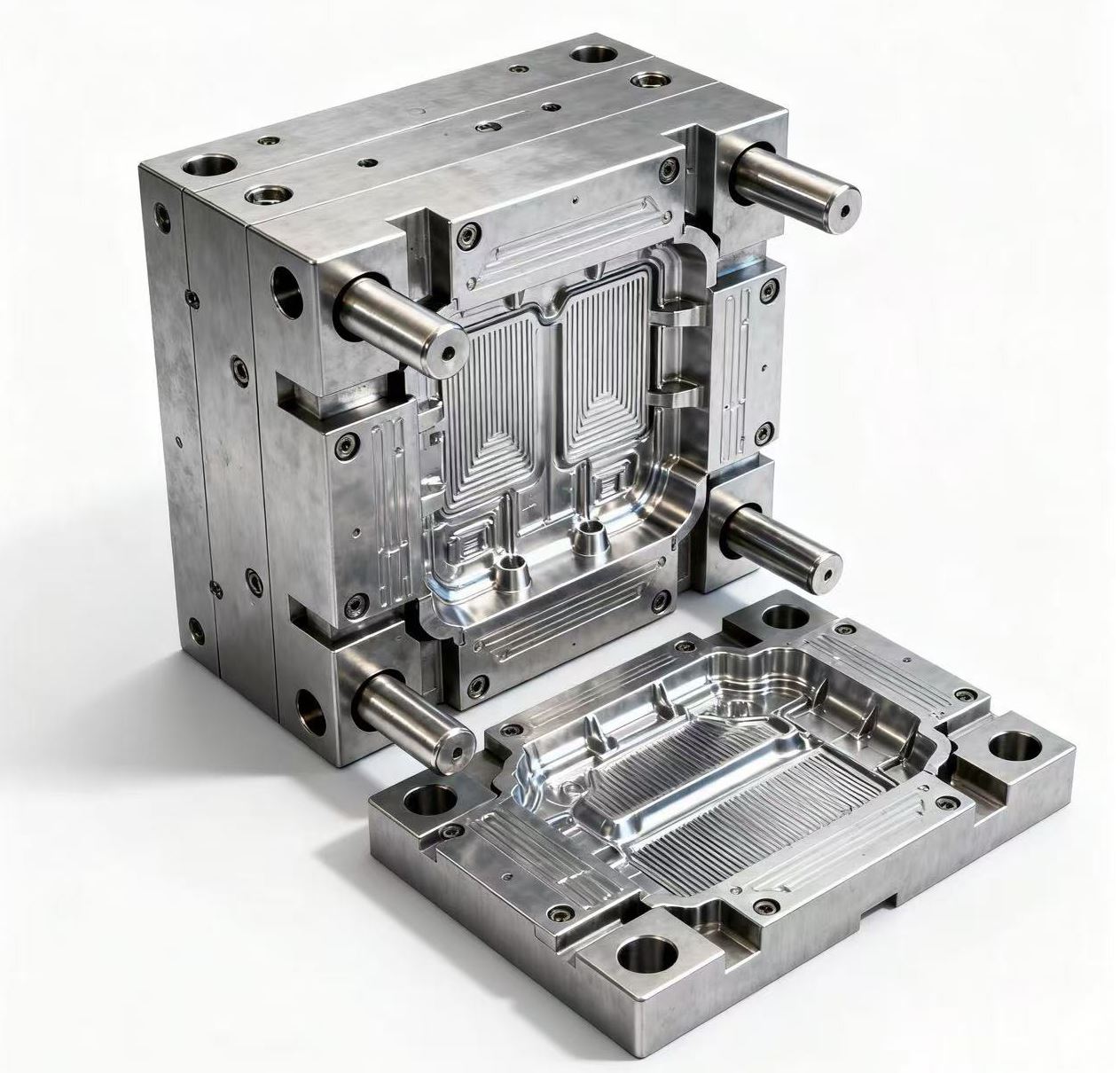
This is the point that gets copied wrongly across a lot of supplier pages, including some we have written ourselves. ISO 20457 is titled Plastics moulded parts — Tolerances and acceptance conditions. Its scope is injection moulding, injection compression moulding, transfer moulding, compression moulding and rotational moulding of non-porous parts in thermoplastics, thermoplastic elastomers and thermosets. It is built around moulding shrinkage, shrinkage anisotropy, parting lines, draft angles and warpage — the deviations a mould produces.
A machined part has none of those. It is cut from extruded or compression-moulded stock, so the shrinkage happened in the stock, before the geometry existed. Applying a moulded-part table to a machined part means quoting a tolerance budget for a process that was never used.
ISO 20457:2018 was withdrawn on 6 August 2026 and replaced the same day by ISO 20457:2026, Edition 2, which adds limits of technical manufacturability for direct tolerances and aligns the drawing default with ISO 8015
The standard does state that it is applicable to other plastic processes if agreed to by the contractual parties. That is a contract-freedom clause, not a technical claim — it means two companies may choose to adopt it, not that it fits machining
DIN 16901, the older plastic tolerance standard still quoted by some shops, was withdrawn in October 2009. It does not fill the gap either
So a supplier page that tells you to specify ISO 20457 for a CNC machined plastic part is telling you to apply a moulding standard to a machining job. The tolerances will be wrong in both directions — too loose on features the cutter holds easily, too tight on features the material will not hold at all.
What Governs a CNC Machined Plastic Part
There is no dedicated ISO standard for general tolerances on machined plastics. Industry practice is to use ISO 2768-m as the default and add the material-specific conditions that the standard does not address. This works because the ISO 2768 values are a statement about the machine, and the extra conditions are a statement about the material.
What the material does after machining is the reason a plastics drawing needs more than a class letter:
Thermal expansion: unfilled plastics move 5 to 15 times more than aluminium for the same temperature change, so a 100 mm PA6 part changes 0.1 mm or more between a 20 °C inspection room and a 30 °C loading bay
Moisture absorption: PA and POM take on water and swell; a nylon part measured dry and measured conditioned can differ by more than the tolerance band
Creep: sustained load moves the part after it has been accepted, so a dimension checked on day one may not be the dimension in service
Stress relaxation: machining leaves stress in the skin, and thin walls bow over the following days as it releases
The fix is three lines on the drawing, covered further down. With them in place, achievable figures for machined plastics look like this — these are shop capability numbers, not standard values:
|
Material
|
Practical default
|
What limits it
|
|---|---|---|
|
POM (acetal)
|
±0.05 mm
|
Very stable to cut; the usual baseline for engineering plastics
|
|
PEEK
|
±0.02 mm, ±0.01 mm on turning
|
Dimensionally the most predictable; cost is the constraint, not accuracy
|
|
PC, PMMA
|
±0.05 mm
|
Stress release and edge chipping on transparent grades
|
|
PA (nylon)
|
±0.10 mm
|
Moisture; must be conditioned before measurement
|
|
PTFE
|
±0.10 mm
|
Creep under load, high expansion; thin walls move more
|
For a metal part, the equivalent figures at Eastmaster are ±0.05 to 0.1 mm as general tolerance, ±0.02 to 0.05 mm where the drawing asks for it, ±0.01 mm with a finishing pass, and below ±0.005 mm the process category changes rather than the tolerance. Those are the numbers we quote against, and they are the same numbers in our design guideline sheet.
How to Write It on a Drawing
Title block, metal part: "General tolerances ISO 2768-m". Add the year to fix the edition — "ISO 2768:2026-m" once Edition 2 is published, "ISO 2768-1:1989-m" until then, because the two are not interchangeable in a dispute
Title block, plastic part: "General tolerances ISO 2768-m" plus "ISO 20457 not applicable — machined from stock" if the customer's template expects a plastics standard and you want the reason on record
Measurement condition, plastic part: "All dimensions measured at 20 °C ± 2 °C after 48 h conditioning at 23 °C / 50 % RH"
Critical features: explicit ± values or GD&T callouts, because the general tolerance is a floor for everything else, not a target
Geometrical defaults on a new drawing: a note under ISO 22081, or individual form and orientation callouts where the function needs them
One habit worth keeping: state the edition. Standards get withdrawn, and a drawing that says "ISO 2768-m" without a year will be read against whatever edition the shop happens to hold.
How to Write It on a Purchase Order
"All untoleranced dimensions per ISO 2768-m" — one line, and it settles the argument before it starts
Material and grade, not just the family: PA6 rather than "nylon", POM-C rather than "acetal". Grade changes both machinability and dimensional behaviour
Conditioning and measurement temperature for any plastic part, otherwise the inspection result depends on the weather
Inspection requirement: first article report, or CMM report on named dimensions. "General tolerance applies" is not an inspection plan
If you want automatic rejection on any overshoot, say so. Under the 1989 text Clause 6 gave the supplier a function-based defence; Edition 2 removes it, but a purchase order written against the old edition may still carry the assumption
Five Mistakes That Cost Money
Specifying ISO 20457 for a machined plastic part. It is a moulding standard; the tables assume shrinkage that machining does not produce
Writing "ISO 2768-mK" on a new drawing. The K class came from a standard withdrawn in 2021
Tightening every dimension to ±0.05 mm because the part is "precision". Cost rises faster than accuracy above class f, and most of the tightened features have no function that needs them
Leaving measurement conditions off a plastics drawing. Two inspectors in two rooms will disagree about the same part
Relying on the function-based rejection clause. It existed in the 1989 text and does not exist in Edition 2
General Tolerance Checklist
☐ Standard and edition named in the title block
☐ Tolerance class chosen against function, not against habit — m for most work, f where it is needed
☐ Geometrical defaults handled under ISO 22081, not ISO 2768-2
☐ No reliance on the deleted broken-edge table for chamfers and external radii
☐ Material and grade specified
☐ Measurement temperature and conditioning state specified for plastics
☐ Critical dimensions carry their own tolerance rather than leaning on the general one
☐ Acceptance rule stated if you want automatic rejection on overshoot
☐ Supplier has confirmed the class is inside their documented capability
Why Buyers Send Tolerance-Critical Work to Eastmaster
At Eastmaster Manufacturing Limited we machine to these standards daily, in metals and in engineering plastics, and we quote against the numbers above rather than against a theoretical minimum.
ISO 9001 and ISO 13485 quality management with documented tolerance verification
CMM inspection for general and specific tolerances, on a programme written per part
Temperature-controlled inspection at 20 °C ± 1 °C, which is what makes a plastic part measurement mean anything
Metals from aluminium and stainless to titanium and brass; engineering plastics including POM, PEEK, PA, PC and PTFE, all machined from stock — we do not mould, so we have no reason to sell you a moulding standard
DFM review before the first chip, where tolerance conflicts and unachievable callouts get flagged on paper
D-U-N-S 66-849-8033
Send your drawing and we will confirm which class applies, which features need their own tolerance, and what the part will actually cost at that class — usually within one working day.
Questions Buyers Ask
Is ISO 2768 still valid in 2026?
ISO 2768-1:1989 was withdrawn on 9 November 2026. ISO 2768 Edition 2 replaces it and is in the final publication stage. The linear and angular tables did not change, so existing drawings still read correctly, but new drawings should name the edition.
Can I use ISO 2768 for a plastic part?
Yes, and for a machined plastic part it is the usual choice — with measurement conditions added. What you cannot use is ISO 20457, which covers moulded parts rather than machined ones.
Why does my drawing say ISO 2768-mK and does it still work?
The K refers to ISO 2768-2, withdrawn in 2021 and replaced by ISO 22081:2021. Most shops will still apply K out of habit, so the part will be made as intended, but the reference is dead. Reissue the note under ISO 22081 when you next revise the drawing.
What tolerance can you actually hold on POM or PEEK?
±0.05 mm is routine on POM, and PEEK holds ±0.02 mm, or ±0.01 mm on turned features under good process control. Below that the material, not the machine, becomes the limit.
Does a tighter general tolerance improve the part?
No. A general tolerance sets what is accepted, not what works. Tightening the default on a whole drawing raises cost across every feature and fixes nothing that a targeted callout would not fix for less.

• Email: info@eastmaster.com
• Phone: +86 755 22676100
• WhatsApp / WeChat available on the right side.
Machining Parts Design: 12 Rules That Cut Cost