Thick Wall Injection Molding: Design Rules, Defects & Solutions Guide
Thick Wall Injection Molding: A Complete Guide to Design, Defects, and Solutions

When you need a strong plastic part that can handle heavy loads, thick wall injection molding is often the answer. But "thick" in injection molding comes with real challenges — sink marks, internal voids, very long cycle times, and higher costs. This guide explains what thick wall molding is, what goes wrong, and how to get it right.
Based on years of injection molding experience at Eastmaster Manufacturing Limited in Shenzhen, China.
What Is Thick Wall Injection Molding?(H2)
Standard injection molding typically uses wall thickness between 1-3 mm. Thick wall injection molding refers to parts with walls thicker than 4 mm — sometimes up to 25 mm for special applications like industrial pipe fittings, heavy-duty housings, and structural components.
Common applications include:
• Industrial valves and pipe fittings
• Heavy-duty housings and enclosures
• Automotive structural components
• Large containers and bins
• Medical device housings
The 4 Big Challenges of Thick Wall Molding(H2)
1. Sink Marks(H3)
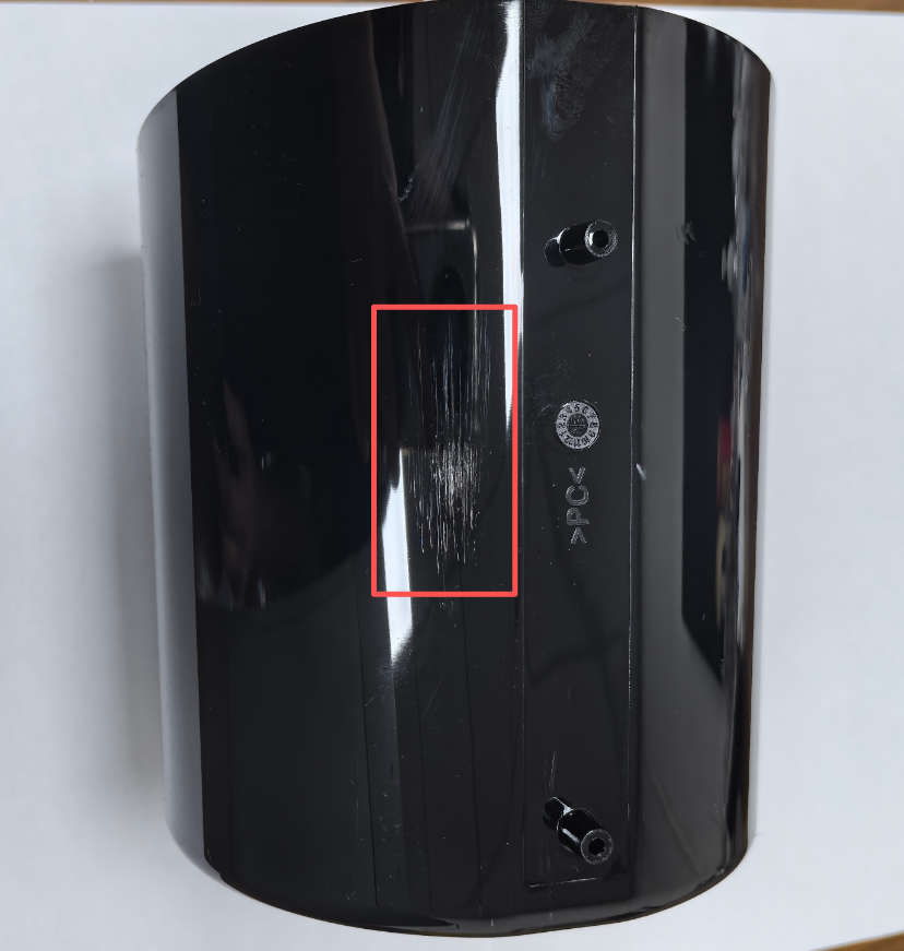
This is the #1 problem. The outer surface cools and hardens first, while the thick inner core stays molten longer. As the core shrinks, it pulls the surface inward, creating a visible depression. Sink marks appear most often above ribs, bosses, and thick sections.
The physics are simple: plastics shrink as they cool (typically 0.5-3% depending on material). Where mass is concentrated, there is more volume to lose. Without enough packing pressure to feed extra material into the thick section before the gate freezes, the surface collapses inward.
2. Internal Voids(H3)
Thick sections cool from the outside in. The trapped molten plastic in the center shrinks but has no extra material to fill the gap, creating air pockets inside the part. These voids weaken the part structurally and are often only found by X-ray or CT scan inspection — too late for mass production.
3. Very Long Cycle Times(H3)
Cooling time grows with the square of wall thickness. Doubling the wall thickness roughly quadruples the cooling time. For example:
• 2 mm wall: about 15 seconds cooling
• 4 mm wall: about 60 seconds cooling
• 6 mm wall: over 100 seconds cooling
This directly raises your per-part cost through higher energy use and lower machine throughput.
4. Warpage(H3)
Uneven wall thickness causes uneven cooling. Thick areas stay hot longer and shrink more than thin areas, creating internal stresses that warp the part after ejection. Large flat parts with localized thick features (like logos or bosses) are the worst offenders.
Design Rules That Actually Work(H2)
The 50-60% Rule for Ribs and Bosses(H3)
Keep rib and boss wall thickness at 50-60% of the main wall thickness. A rib that is too thick at its base creates a local thick spot and causes sink marks on the opposite surface. If you need more strength, add more ribs or bosses — do not make them thicker.
|
Nominal Wall (mm) |
Max Rib/Boss Wall at 0.6x (mm) |
Max at 0.7x (use sparingly) |
|
1.5 |
0.9 |
1.05 |
|
2.0 |
1.2 |
1.4 |
|
2.5 |
1.5 |
1.75 |
|
3.0 |
1.8 |
2.1 |
|
3.5 |
2.1 |
2.45 |
Uniform Wall Thickness(H3)
Try to keep walls as even as possible. When thickness changes are needed, use gradual transitions (at least 3:1 ratio of length to thickness change) instead of sudden steps. This reduces uneven cooling and stress concentration.
Core Out Thick Sections(H3)
Instead of solid thick walls, hollow out the inside. This keeps strength while reducing the thermal mass that causes sink marks and long cooling times. For bosses, use core holes and gussets instead of solid mass.
Good Gate Design(H3)
Place the gate near the thickest section so packing pressure can reach the area that needs it most. Use a gate large enough to stay open during the packing phase. If the gate freezes too early, no amount of holding pressure will help.
Process Tips for Thick Wall Parts(H2)
• Dry materials properly: Hygroscopic materials (Nylon, PC, ABS, PET) must be dried to spec before molding. Even small amounts of moisture cause splay marks and voids.
• Multi-stage packing pressure: Use 2-3 stages with decreasing pressure. This provides sustained compensation for shrinkage throughout solidification.
• Hold until gate freeze: Do a gate freeze test to find the right hold time. If hold ends before the gate freezes, melt flows back out and thick sections shrink without compensation.
• Extend cooling time: Do not rush ejection. The part must cool below the material's heat deflection temperature before ejection, especially in thick sections.
• Consistent mold temperature: Keep the temperature difference below 10°C between cavity and core to prevent uneven shrinkage.
When to Consider Alternatives(H2)
If your part needs walls thicker than 10 mm, or you only need a few pieces, consider:
• CNC machining from solid plastic blocks for low volumes — no mold cost, faster turnaround
• Compression molding for very large thick parts
• Reaction injection molding (RIM) for large structural parts with lower tooling cost
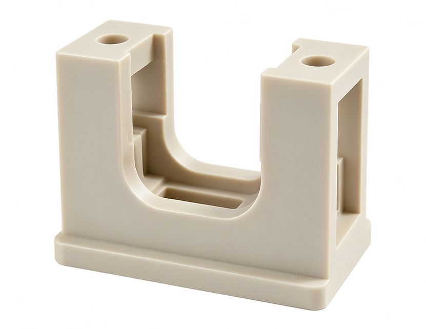
For low-volume thick parts, CNC machining from solid plastic stock (PEEK, POM, Nylon, etc.) can be faster and more cost-effective than building a thick-wall injection mold.
Why Choose Eastmaster for Thick Wall Parts(H2)
At Eastmaster Manufacturing Limited, we review every thick wall design for manufacturability before building the mold. Our DFM (Design for Manufacturability) check catches sink-prone geometry early, saving costly mold modifications later.
• Free DFM review for all injection molding projects
• Mold flow simulation to predict sink and void locations
• >In-house mold making with optimized cooling channel design
• >CNC machining capability for low-volume thick wall parts
• ISO 9001 and ISO 13485 certified quality management
• D-U-N-S verified: 66-849-8033
Contact Eastmaster with your part drawings for a free DFM review and quote — typically within 24 hours.
Email:info@eastmaster.com Phone: +86 755 22676100
Splay Marks in Injection Molding: Causes, Fixes, and Prevention